Tampilkan postingan dengan label CKD Valve. Tampilkan semua postingan
Lubricant level switches SKF for Oils and Fluid Greases

Lubricant level switches SKF for Oils and Fluid Greases

Lubricant level switches for oils
A visual indicator in the form of an oil gauge glass, is installed on most reservoirs. It lets the operator read the lubricant level. Float switches with one to three output signals are generally used for electrical monitoring.

Design of a float switch: A permanent magnet accomodated in the float body operates a reed contact located in the tubular guide. Multiple contacts can be installed in the tubular guide at different heights, thus making it possible to flag different filling levels. An early warning can also be generated (e.g. 25 mm before the minimal lubricant level is reached).

Lubricant level switches for fluid greases

The same principle does not apply to fluid greases. In this case, capacitive proximity switches are used which normally only have one signal output. Multiple proximity switches are required in order to show multiple lubricant levels.Lubricant level switches for greases

Mechano-electrical, opto-electrical or proximity switches are used to emit electrical signals. A separate electrical switch with a discrete signal output must be used for each lubricant level to be read.

Tags: float level switches, guided radar level sensors, Level indicators, Level sensors, pendulum, rotary paddle switches

Actuator Oil Filter

Actuator Oil Filter

3-valve manifold, actuator, Actuator CKD, Actuator Oil Filter, After cooler series HAA - HAW, air catch sensor, air suction filter,Air Tank Series AT, Automation Technology, Auxiliary Relay,block valve for vacuum, booster relay, Circuit Protector, CKD Valve, clean gas filter, Cleaning solvent, Compact low hydraulic Cylinder,conflat aluminum flage, Control Relay, Control System, cutting oil filter, defleon, digital pressure switch, digital pressure switch smc, EDM Consumables and Parts, EDM Machines, ELCB, Electrical Motors, electro-pneumatic regulator, flow switch, Fluid Control Products, Frenic, Fuji Electric, heatless air dryer,HEPO Filter element, Honeycomb element, Industrial Automation, Input Output, Inverter, Line Filter, lock-up valve,Lubricator-check, Magnetic Contactor, Magnetic Motor Starter, Magnetic Separator,Mainline filter, MCB, MCCB, Membrandt element, Micromist Lubricator, mist separator, Mitsubishi Electric, odour removal filter,oil cooler, Oil Filter, OMRON, positioner,Power Supply, PP Fiber element, pressure switch, process pump, Processor,Programmable Logic Controllers (PLC), Programming Unit, refrigerated air dryer,heatless air dryer, Return Line Filter, rotary actuator, Rotary cylinder,self-seal fittings, Solenoid Valve, Solenoid valve CKD, Suction Filter,Suction Guard, suction plate, Temperature Controllers,Thermal Overload Relay, vacuum pad, vacuum unit and ejector, water separator, Wire Cloth,
FKE Level Transmitter Fuji Electric

FKE Level Transmitter Fuji Electric

Fuji Electric FKE Level Transmitter Specification
Accurately measure liquid level
• Manufactured by Fuji Electric
• High accuracy 0.1 and 0.2%
• Range ± 32 to 5000 m bar
• Measures liquid, gas, or vapor
• Hazardous area approvals
• Minimum environmental influence
• Fuji/ HART® bilingual communications protocol and FOUNDATION™ fieldbus and Profibus™ compatibility
• Application flexibility
• Programmable output linearization function
• Burnout current flexibility
• Dry calibration without reference pressure ,
Solenoid Valve CKD 4F011 - 4F141

Solenoid Valve CKD 4F011 - 4F141

Solenoid Valve CKD Types:

A4F011
A4F021
4F011
4F021
4F111
4F121
4F131
4F141
CKD PNEUMATIC CYLINDER
Lubrication type without switch
SCS-LB-125-B-50

Oil-free type without switch
SCS-N-LB-125-B-50

Oil-free type with switch
SCS-LN LB 125 B 50 R0

CKD Pneumatic - Cylinder SCA2-P-LB-40B-100
CKD PNEUMATIC CYLINDER
Double acting, stroke adjustable type ( extend) SCA2-P Series

CKD : Solenoid Valve AB41
2 port direct acting solenoid valve : Open when energized, close when energized
GENERAL PURPOSE VALVE AB31· AB41· AB42 SERIES Discrete valve

• Direct acting poppet structure • Port size : Rc1/ 8, Rc1/ 4, Rc3/ 8, Rc1/ 2
Valve and Pneumatic Products

Valve and Pneumatic Products

Solenoid valve SMC, actuator, Compact hydraulic Cylinder CKD, Compact low hydraulic Cylinder SMC, Low pressure hydraulic Cylinder SMC, hydraulic Cylinder with improved water resitance SMC, Suction Filter, Suction Guard, Line Filter, Return Line Filter, Solenoid valve CKD, CKD Valve, Actuator CKD, Oil Filter, oil cooler, Magnetic Separator, HEPO Filter element, Honeycomb element, SMC Filter, Membrandt element, Wire Cloth element, Filter for Cleaning solvent, PP Fiber element, defleon, deethane water alkalescence, hydrauclic oil, lube oil, cutting oil filter, After cooler series HAA - HAW, Air Tank Series AT, Mainline filter, refrigerated air dryer, heatless air dryer, mist separator, odour removal filter, water separator, clean gas filter, vacuum unit, vacuum ejector, vacuum pressure switch, suction plate, vacuum pad, air suction filter, free mount cylinder with vacuum pad, filter regulator, flow switch, pressure switch, digital pressure switch smc, air catch sensor, booster relay, lock-up valve, 3-valve manifold, positioner, electro-pneumatic regulator, L-shaped aluminum valve for extra high vacuum, process pump, block valve for vacuum, conflat aluminum flage, digital pressure switch, Rotary cylinder, rotary actuator, Micromist Lubricator, Lubricator-check, self-seal fittings series KC SMC.
Installing The CPU Unit and I/O Unit OMRON PLC Step by Step

Installing The CPU Unit and I/O Unit OMRON PLC Step by Step

Installing PLC Step by step using OMRON PLC as sample:

1. Panel Installation
Consider PLC operation, maintenance, and surrounding conditions when installing the PLC in a panel or cabinet. The operating temperature range for the PLC is 0°C to 55°C Be sure that there is adequate ventilation for cooling;
• Allow enough space for air circulation.
• Do not install the PLC above equipment that generates a large amount of heat, such as heaters, transformers, or large resistors.
• Install a cooling fan or system when the ambient temperature exceeds 55°C
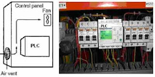
The small PLC in panel


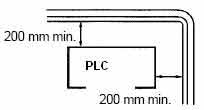
Power lines & high-voltage equipment can cause electrical noise in the PLC; • Do not install the PLC in a panel or cabinet with high-voltage equipment • Allow at least 200 mm between the PLC and nearby power lines See the picture below;

Make sure that the PLC can be accessed for normal operation and maintenance;
• Provide a clear path to the PLC for operation and maintenance. High-voltage equipment or power lines could be dangerous if they are in the way during routine operations
• The PLC will be easiest to access if the panel or cabinet is installed about 3 to 5 feet above the floor

2. Installing the CPU Unit and I/O Unit
The small PLC must be installed in the position shown below to ensure adequate cooling.
See the picture below;


Do not install the small PLC in either of the following positions.

The small PLC can be installed on a horizontal surface or on a DIN track. See the picture below;

Lower the small PLC so that the notch on the back of the PLC catches the top of the DIN Track. Push the PC forward until the lock snaps into place. See the picture below;

For the big PLC before installing, the Units have to compiled one by one. There is no single Unit that can be said to constitute a Rack PLC. To build a Rack PLC, we start with a Backplane. The Backplane for the Omron PLC is shown below.

The Backplane is a simple device having two functions. The first is to provide physical support for the Units to be mounted to it. The second is to provide the connectors and electrical pathways necessary for connecting the Units mounted to it. The core of the PLC is the CPU. The CPU contains the program consisting of the series of steps necessary for the control task. The CPU has a built-in power supply, and fits into the rightmost position of the Backplane.

The CPU of the big PLC has no I/O points built in. So, in order to complete the PLC we need to mount one or more I/O Units to the Backplane. Mount the I/O Unit to the Backplane by locking the top of the I/O Unit into the slot on the Backplane and rotating the I/O Unit downwards as shown in the following diagram. Press down on the yellow tab at the bottom of the slot, press the I/O Unit firmly into position, and then release the yellow tab.

The figure below shows one I/O Unit mounted directly to the left of the CPU.

I/O Units are where the control connections are made from the PLC to all the various input devices and output devices. As you can see from the figure above, there is still some space available on the left side of the Backplane. This space is for any additional I/O Units that may be required.The figure below shows a total of eight I/O Units mounted to the Backplane.

After the big PLC compiled in the backplane then the big PLC can be installed on the DIN Rail. The DIN Rail Mounting Bracket shown below is necessary for mounting the PLC to the DIN Rail.

The following diagram is a view of the back of the Backplane. Attach one Mounting Bracket to the left and right sides of the Backplane as shown below.

Mount the Backplane to the DIN Rail so that the claws on the Mounting Brackets fit into the upper portion of the DIN Rail as shown below.

Loosen the screws attaching the Mounting Brackets to the Backplane. Slide the Backplane upward as shown below so that the Mounting Bracket and Backplane clamp securely onto the DIN Rail. Tighten the screws.


3. Installing the Expansion Unit or Expansion I/O Unit
The Expansion Unit or Expansion I/O Unit are usually attached when amount of I/O devices to be controlled increase its amount over than capacities of the existing I/O Unit or attached when needed to a special need like temperature sensor. The following shown the example of Expansion Units.

Expansion Unit of the small PLC


Expansion Unit of the big PLC

For the small PLC use the following procedure when connecting an Expansion Unit or Expansion I/O Unit;Remove the cover from the CPU Unit’s or the Expansion I/O Unit’s expansion connector. Use a flat-blade screwdriver to remove the cover from the Expansion I/O Connector.


Insert the Expansion I/O Unit’s connecting cable into the CPU Unit’s or the Expansion I/O Unit’s expansion connector.


Replace the cover on the CPU Unit’s or the Expansion I/O Unit’s expansion connector.


For the big PLC use the following picture when connecting an Expansion Unit or Expansion I/O Unit;


4. Installing I/O devices
I/O devices are attached at the place have been determined in the work plan and wiring diagram. For switches are usually attached at the panel while the sensor, selenoid and motor is usually placed at the machine to be controlled.


5. Wiring and connections
Duct Work
Hanging Ducts If power cables carrying more than 10 A 400 V, or 20 A 220 V must be run alongside the I/O wiring (that is, in parallel with it), at least 300 mm must be left between the power cables and the I/O wiring as shown below.


Floor Ducts If the I/O wiring and power cables must be placed in the same duct (for example, where they are connected to the equipment), they must be shielded from each other using grounded metal plates.


Conduits if Separating the PLC I/O lines, power and control lines, and power cables, as shown in the following diagram.


I/O connections
Connect the I/O Devices to the I/O Units. Use 1.25-mm2 cables or larger The terminals have screws with 3.5-mm diameter heads and self-raising pressure plates. Connect the lead wires to the terminals as shown below. Tighten the screws with a torque of 0.8 N _ m.

If you wish to attach solderless type terminals to the ends of the lead wires, use terminals having the dimensions shown below.

The following diagrams show the input configurations. This input configuration depend on specification of the Input Unit will be used. See the specification before install.

The following diagrams show the input configurations. This output configuration depend on specification of the Output Unit will be used. See the specification before install.

Industrial Automation Advantages and disadvantages

Industrial Automation Advantages and disadvantages

What is Industrial Automation?

Automation is the use of control systems (such as numerical control, programmable logic control, and other industrial control systems), in concert with other applications of information technology (such as computer-aided technologies [CAD, CAM, CAx]), to control industrial machinery and processes, reducing the need for human intervention.

In the scope of industrialization, automation is a step beyond mechanization by use of robotic devices to complete manufacturing tasks. Whereas mechanization provided human operators with machinery to assist them with the physical requirements of work, automation greatly reduces the need for human sensory and mental requirements as well. Processes and systems can also be automated.

In this day and age of computers, industrial automation is becoming increasingly important in the manufacturing process because computerized or robotic machines are capable of handling repetitive tasks quickly and efficiently. Machines used in industrial automation are also capable of completing mundane tasks that are not desirable to workers. In addition, the company can save money because it does not need to pay for expensive benefits for this specialized machinery. There are both pros and cons for a company when it comes to industrial automation.

On the plus side, with soaring healthcare costs, paid days off, vacation time, and other costly employee benefits, companies can save money with industrial automation. While robotic machinery can initially be extremely expensive, the loss of monthly wages for production workers leads to incredible savings for the company. While machinery used for industrial automation can break down, it does not happen often. If it does, only a handful of maintenance or computer engineers are needed to handle repairs and get lines running smoothly again.

In addition, many plants hire dozens of production workers for a variety of shifts and need to close on certain days. Industrial automation, however, allows a company to run the plant twenty-four hours a day, 365 days a year, without paying overtime. This fact alone can add up to significant savings.

A company that employs forty-eight factory workers on three different shifts and closes on weekends, for example, can save thousands of dollars with industrial automation. This is particularly true if weekend work is necessary, which means overtime pay of time and a half must be paid for Saturday work and double-time for Sunday. This equates to an additional twelve hours of pay per employee. Of course, life insurance, 401K benefits, dental insurance, health insurance, pension coverage, and disability also contribute to the expense.

Industrial automation can eliminate the need for all forty-eight jobs. The robotic machinery used for industrial automation may only involve a monthly payment until the machinery is paid for, a couple technicians to keep the robotic machinery running, and electricity costs. Unfortunately for workers, industrial automation can eliminate thousands of jobs. As the workforce decreases and the cost of living increases, many families struggle to make ends meet as their jobs are replaced by high-tech machines.

Advantages and disadvantages

The main advantage of automation are:

  • Replacing human operators in tedious tasks.
  • Replacing humans in tasks that should be done in dangerous environments (i.e. Fire, space, volcanoes, nuclear facilities, under the water, etc)
  • Making task that are beyond the human capabilities such as handle too heavy loads, too large objects, too hot or too cold sustances or the requirement to make things too fast or too slow.
  • Economy improvement. Sometimes and some kinds of automation implies improves in economy of enterprises, society or most of humankind. For example, when an enterprise that has invested in automation technology recovers its investment; when a state or country increases its income due to automation like Germany or Japan in the XX Century or when the humankind can use the internet which in turn use satellites and other automated engines.

The main disadvantages of automation are:

  • Technology limits. Nowadays technology is not able to automatizate all the desired tasks.
  • Initial costs are relative high. The automation of a new product required a huge initial investment in comparison with the unit cost of the product, although the cost of automation is spread in many product batches. The automation of a Plant required a great initial investment too, although this cost is spread in the products to be produced.
Industrial Automation Tools

Industrial Automation Tools

Devices Used for Industrial Automation

Many different types of devices used for automation exist. These devices include a range from SCADA, used for data and control, to HMI, in which users adapt a program.

Different Types of Industrial Automation Tools:

  • Programmable Logic Controller (PLC)
  • Artificial Neural Network (ANN)
  • Distributed Control System (DCS)
  • Human Machine Interface (HMI)
  • Supervisory Control and Data Acquisition (SCADA)
  • Programmable Automation Controller (PAC)
  • Distributed Control System (DCS)
  • Batch Management System (BMS)
  • Manufacturing Execution System (MES)
  • Laboratory Information Management System (LIMS)
  • Instrumentation
  • Motion Control
  • Robotics
  • Simulatio
  • etc

PLC Input Ouput (I/O)

PLC Input Ouput (I/O)

Input - Output I/O
PLC consists of a processor unit of I/O cards mounted in local racks. Early PLCs did tend tobe arranged like this, but in a large and scattered plant with this arrangement,all signals have to be brought back to some central point inexpensive multicore cables. It will also make commissioning and faultfinding rather difficult, as signals can only be monitored effectively ata point possibly some distance from the device being tested.In all bar the smallest and cheapest systems, PLC manufacturers therefore provide the ability to mount I/O racks remote from the processor, and link these racks with simple (and cheap) screened singlepair or fibre optic cable. Racks can then be mounted up to severalkilometres away from the processor.

There are many benefits from this. It obviously reduces cable costs asracks can be laid out local to the plant devices and only short multicorecable runs are needed. The long runs will only need the communication cables (which are cheap and only have a few cores to terminate at eachend) and hardwire safety signals.Less obviously, remote I/O allows complete units to be built, wired toa built-in rack, and tested offsite prior to delivery and installation. Thepulpit in Figure contains three remote racks, and connects to thecontrolling PLC mounted in a substation about 500m away, viaa remote I/O cable, plus a few power supplies and hardwire safetysignals. This allowed the pulpit to be built and tested before it arrivedon site. Similar ideas can be applied to any plant with I/O that needs tobe connected to a PLC.If remote I/O is used, provision should be made for a program terminalto be connected local to each rack. It negates most of the benefits if the designer can only monitor the operation from a central control roomseveral hundred metres from the plant. Fortunately, manufacturershave recognized this and most allow programming terminals to beconnected to the processor via similar screened twin cable.

PLC Output Cards
Output cards again require some form of isolation barrier to limit damage from the inevitable plant faults and also to stop electrical ‘noise’ corrupting the processor’s operations. Interference can be more of a problem on outputs because higher currents are being controlled by Computers and industrial

Computers and industrial control 25 the cards and the loads themselves are often inductive (e.g. solenoid and relay coils). There are two basic types of output card. Eight outputs are fed from a common supply, which originates local to the PLC cubicle (but separate from the supply to the PLC itself). This arrangement is the simplest and the cheapest to install. Each output has its own individual fuse protection on the card and a common circuit breaker. It is important to design the system so that a fault, say, on load 3 blows the fuse FS3 but does not trip the supply to the whole card, shutting down every output. This topic, called ‘discrimination’, is discussed further in Chapter. A PLC frequently has to drive outputs which have their own individual supplies.

A typical example is a motor control centre (MCC) where each starter has a separate internal 110-V supply derived from the 415-V bars. The card arrangement could not be used here without separate interposing relays (driven by the PLC with contacts into the MCC circuit). An isolated output card, has individual out-puts and protection and acts purely as a switch. This can be connected directly with any outside circuit. The disadvantage is that the card is more complicated (two connections per output) and safety becomes more involved. An eight-way isolated output card, for example, could have voltage on its terminals from eight different locations.

Relay outputs can be used (and do give the required isolation) but are not particularly common. A relay is an electromagnetic device with moving parts and hence a finite limited life. A purely electronic device will have greater reliability. Less obviously, though, a relay-driven inductive load can generate troublesome interference and lead to early contact failure. Optical isolation is again used to give the necessary separation between the plant and the PLC system. Diode D1 acts as a spike suppression diode to reduce the voltage spike encountered with inductive loads. The output state can be observed on LED1. If NPN transistors are used, a current sinking card can be made. AC output cards invariably use triacs, a typical circuit being. Triacs have the advantage that they turn off at zero current in the load, which eliminates the interference as an inductive load is turned off. If possible, all AC loads should be driven from triacs rather than relays.

An output card will have a limit to the current it can supply, usually set by the printed circuit board tracks rather than the output devices. An individual output current will be set for each output and a total overall output . Usually the total allowed for the card current is lower than the sum of the allowed individual outputs.

PLC Input Cards
Internally a computer usually operates at 5 V DC. The external devices (solenoids, motor starters, limit switches, etc.) operate at voltages up to 110 V AC. The mixing of these two voltages will cause severe and possibly irreparable damage to the PLC electronics. Less obvious problems can occur from electrical ‘noise’ introduced into the PLC from voltage spikes on signal lines, or from load currents flowing in AC neutral or DC return lines. Differences in earth potential between the PLC cubicle and outside plant can also cause problems.

The question of noise is discussed, but there are obviously very good reasons for separating the plant supplies from the PLC supplies with some form of electrical barrier. This ensures that the PLC cannot be adversely affected by anything happening on the plant. Even a cable fault putting 415 V AC onto a DC input would only damage the input card; the PLC itself (and the other cards in the system) would not suffer. This is achieved by optical isolators, a light-emitting diode and photo-electric transistor linked together.

Protection of the PLC from outside faults. The PLC supply L1/N1 is separate from the plant supply L2/N2 switch on. Because there are no electrical connections between the diode
and the transistor, very good electrical isolation (typically 1–4kV) is achieved. A DC input can be provided. When the push-button is pressed, current will flow through D1, causing TR1 to turn on, passing the signal to the PLC internal logic. Diode D2 is a light-emitting diode used as a fault-finding aid to show when the input signal is present. Such indicators are present on almost all PLC input and output cards. The resistor R sets the voltage range of the input. DC input cards are usually available for three voltage ranges: 5V (TTL), 12–24V, 24–50V. A possible AC input circuit. The bridge rectifier is used to convert the AC to full wave rectified DC. Resistor R2 and capacitor C1 act as a filter (of about 50ms time constant) to give a clean signal to the PLC logic. As before, a neon LP1 acts as an input signal indicator for fault finding, and resistor R1 sets the voltage range. The isolation barrier and monitoring LEDs can be clearly seen. This card handles eight inputs and could be connected to the outside world.
 
Support : Creating by | PTNGA | Metal
Copyright © 2011. Mitsubishi & Fuji Electric Indonesia - All Rights Reserved
Created by Website Published by Product | Distributed By: Toko
Proudly powered by Blogger