Tampilkan postingan dengan label Automation Technology. Tampilkan semua postingan
Inverter FRN G1E-4E Frenic Mega (G1E) Fuji Electric

Inverter FRN G1E-4E Frenic Mega (G1E) Fuji Electric

Inverter FRENIC Fuji Electric Types:

FRN 0.4 G1E-4E Frenic Mega(G1E),
FRN 0.75 G1E-4E Frenic Mega(G1E),
FRN 1.5 G1E-4 Frenic Mega(G1E),
FRN 11 G1E-4 Frenic Mega(G1E),
FRN 110 G1E-4 Frenic Mega(G1E),
FRN 132 G1E-4 Frenic Mega(G1E),
FRN 15 G1E-4 Frenic Mega(G1E),
FRN 160 G1E-4 Frenic Mega(G1E),
FRN 2.2 G1E-4 Frenic Mega(G1E),
FRN 200 G1E-4 Frenic Mega(G1E),
FRN 220 G1E-4 Frenic Mega(G1E),
FRN 280 G1E-4 Frenic Mega(G1E),
FRN 30 G1E-4 Frenic Mega(G1E),
FRN 315 G1E-4 Frenic Mega(G1E),
FRN 355 G1E-4 Frenic Mega(G1E),
FRN 37 G1E-4 Frenic Mega(G1E),
FRN 4.0 G1E-4 Frenic Mega(G1E),
FRN 400 G1E-4 Frenic Mega(G1E),
FRN 45 G1E-4 Frenic Mega(G1E),
FRN 5.5 G1E-4 Frenic Mega(G1E),
FRN 500 G1E-4 Frenic Mega(G1E),
FRN 55 G1E-4 Frenic Mega(G1E),
FRN 630 G1E-4 Frenic Mega(G1E),
FRN 7.5 G1E-4 Frenic Mega(G1E),
Converter Kit BBM

Converter Kit BBM

Klockner LPG converter provides complete solution and 110% performance of petrol engine on Auto LPG Fuel.
Klockner gas technology is a amalgamation of a seven new principles and technologies, which we have discovered first time in the world and applied for successfully running of all types of 2 wheelers on LPG Fuel. It is not the all, bike fitted with Klockner gas kit system beats petrol run original Models in terms of power developed, cold starting, fuel efficiency, pick up, pollution, maintenance and engine life.

  • EMR Single kick starting technology

This system ensures first kick-start of engine without touching the Accelerator. In this starting technique Air& Fuel are pre mixed in explosive ratio & fed directly to intake manifold facilitating instant starting.

  • RVO Power Enhancer Technology

This supersaver Reed Valve Operated device specially developed to work in tandem with the gassifire does not allow any fuel wastage by the kit and enhances the power output of the engine, for example:- if an engine has a top speed of 100 Km./hour on petrol then on klockner gas system with this device, ensures that the engine will give a top speed of 105 Km/hour.

Emitting pollution levels also comes to near zero.

Power Enhancer Device

  • Low Pressure Klockner Gassifire

All klockner gas system works on low-pressure systems i.e., Gas cylinder by design, supplies gas fuel at a pressure as low as 0.5 PSI.

KLOCKNER Gassifire is a single stage suction based, twin diaphragm operated precision gas to gas control valve, specially designed to run air cooled single cylinder engines 50 cc to 375 cc 4 stroke as well 2 stroke

Klockner Gassfire

  • MVLPO Gas Container

Gas Containers, Capacities 2.5 kg, 2.2 kg & 2 kg Gas Meter

MVLPO Gas Container is a specially designed system for safe handling & storage of Liquid Gas. MVLPO Gas cylinder are available of capacities 2.5 Kg. (4 Ltr. LPG capacity), 2.2 Kg (3.52 Ltr. LPG capacity) having inbuilt functions like a) Fuel level meter which indicates gas in Kg scale b) Excess pressure release valve / safety valve c) Filler valve (To fill gas from Auto LPG Station/ dispensing units) d) Low pressure gas Output at 0.5 PSI (with double locking valve) installed with a low pressure rugged output regulator, with flow adjustment facility.

OTHER APPLICATIONS :

Klockner gas technology finds endless applications and is extremely useful for applications like: Outboard engines / Fishing Boats / Speed Boats etc. Petrol and kerosene run multipurpose engines used for miscellaneous applications.
Petrol and kerosene run water pump sets. Petrol and kerosene run Portable Generators unto 500 VA to 7 KVA

ALL THESE SYSTEMS ARE DESIGNED TO WITH STAND 5 TIMES THE WORKING PRESSURE)

  • Oil And Dirt Separator

All klockner kits consist of a special filtration system, which enhances the performance of the total system. Protect system from all metallic impurities / rust particle in fuel., Increases the life of the gas cylinder and the total system.

It Prevents any fuel Line choking, Meter Jamming etc. This system also separates the wax

(Scent chemical: – ethyl me captor, C2H5SH) – out of gas hence increasing the life of gassfire components manifolds (no periodic cleaning) of vaporizer necessary as in case of all other vapourisers available for cars.

  • SSJ Ideal Speed control

It is impractical to have constant ideal running of a single cylinder 4 stroke engine with the help of Diaphragm Based Vaporizer, specially in cold conditions. To overcome this problem Solenoid based slow jet speed control technique has been developed.

  • Electronic PWR 2-T oil system

Electronic pulse width regulation oil system is a specially developed 2-T Oil Pump meant for smooth supply of 2-T Oil to 2 Stroke engine and it ensures supply of 2T-Oil in proportion to engine RPM. It enhances engine life & performance.

Power Based Electronic 2-T Oil Pump

ii) GTP Mechanical Oil Pump

This is a mechanical vacuum operated 2T-Oil Pump and is a alternate, direct replacement to electronic PWR 2T oil system. Safest gas system of the world.

h) All klockner LPG Converter kits function on “ lean burn system” and operates at extremely low pressure. Thereby maximizing fuel efficiency and overall system safety. Gassifire releases gas only when the piston of the vehicle generates a stroke, as soon as engines stops for any reason the gas supply to engine cuts of automatically.

Klockner LPG Converter kit consists of the following Sub-Assys: -

  • Dikki /Housing
  • Bracket Assy
  • Drainer Assy
  • Gassifie Assy
  • Solenoid
  • Control Circuit & Wiring
  • Container / Cylinder Assy
  • Regulator Assy
  • Pipe Assy. / Cylinder Belt
  • Nozzle / Ventury Assy
  • Gas Filling Attachment Assy
  • RVO Power Enhancer
  • Electronic PWR 2T-Oil System
  • GTP Mechanical Oil Pump
Sony DCRSRxx Kamera Tembus Pandang

Sony DCRSRxx Kamera Tembus Pandang

Kamera Sony DCRSRxx

Sony DCRSRxx kamera dengan fitur tambahan berupa lensa X-RAY dan Nighshoot yang dapat di gunakan untuk melakukan pengintaian pada malam hari dengan tingkat ketajaman yang maksimal sekalipun di tempat yang sangat gelap pekat.


Spesifikasi utamanya: Sony DCRSRxx HDD HandyCam – Carl Zeiss Lens, 25 x Optical 2.7″ Wide LCD Touch screen, 40 GB HDD, 27h HDD Recording .720 x 576 Standard Definition.


Kamera ini dijual untuk kalangan terbatas karena fitur tambahannya yang jika disalagunakan dapat berakibat merugikan orang lain. Harap diingat jika kamera ini dapat melihat tembus pandang pada seseorang yang menggunakan pakaian berbahan ” NYLON” ataupun SPANDEX FABRIC.

Garmin Release Mobile Navigator

Garmin Release Mobile Navigator

Garmin, a provider of digital map-based navigation services are now ready to release the product for Android phones, IOS and Windows Phone.

Titled Mobile Navigator application was made by Navigon, a subsidiary of Garmin which does focus on developing applications for Pocket PC or smartphone.

Not many features in this application that can be leaked, but one of them is the Cockpit. A feature that allows users to record the speed and aklerasi for 30-minute drive away. Besides Mobile Navigator also provides a map that can be downloaded and updated regularly, this is what makes superior applications.

Garmin GPSMAP® 6000/7000 Series Network Chartplotters
The Evolution of Marine Technology

Unleash never-before-seen power across your helm with the Garmin GPSMAP® 6000/7000 series network chartplotters. Featuring Garmin G Motion™ technology, these ultra-fast chartplotters come standard with high-speed graphical processors that deliver nearly two times the map-drawing agility and performance of their predecessors.

Connect to Your Network
Both the GPSMAP 6000 and 7000 series offer expanded "plug-and-play" access to onboard sensors, with NMEA 2000 and Garmin Marine Network connectivity. So, it's easy to access and control a whole array of network assets from any compatible plotter on your boat: Everything from autopilot and engine sensors to VHF radios, onboard radar, digital sonar, XM WX® satellite weather* with NEXRAD, AIS traffic monitoring, live-cam security video, and more.

Experience BlueChart® g2 Functionality
The GPSMAP 6000 and 7000 series offer support for optional BlueChart g2 Vision SD card data - adding a whole new dimension of exceptional features to your chartplotter.
With BlueChart® g2 Vision® cards, you'll have access such premium features as true 3-D "Mariner's Eye" and underwater "Fish Eye" perspective views, plus Auto Guidance capability to suggest the best passages, and "real picture" aerial photo-reference with marine points-of-interest (POI) location data.

The Performance You Demand
These top-of-the-line multifunction displays offer ultra-smooth map panning and zooming with virtually seamless graphical updating in all dimensions. It's some of the most stunning marine cartographic technology you've ever seen in this class of equipment.

Designed to Move You

With a sleek and streamlined design that complements any cabin, the GPSMAP 6000 and 7000 series offer a variety of mounting options. This flexibility allows you to equip your vessel in a configuration that best suits your needs. And for even more options, you can choose traditional softkey interface on the GPSMAP 6000 series - or step up to the cool efficiency of touchscreen operation on all GPSMAP 7000 series products. The 6000 series displays are sized from 8.4 to 12.1 inches, with the larger unit incorporating an alphanumeric keypad. Both sizes are compatible with an optional wireless remote (sold separately). Then, moving up to the GPSMAP 7000 series, you can go with an even larger 15-inch XGA touchscreen display - or opt for the same XGA resolution in a 12.1-inch diagonal screen configuration. These robust, punishment-tested touchscreen units are compatible with an optional wireless remote and a wireless mouse (both sold separately). And the 15-inch model even has PC monitor input, so you can use it for display of digital presentations, Internet browsers, or other computer applications.


Source: Detik
Automatic Transfer Switch for Emergency Power Supply System

Automatic Transfer Switch for Emergency Power Supply System

Automatic Transfer Switch (ATS) is used for emergency power supply system to switch between two power supply, in order to ensure continuous and reliable electrical power to critical loads. It is primarily used in critical installations, for instance, fire protection system, telecommunication, coal mine and shipping, chemical industry and metallurgy, industrial plants, medical and health care, bank and securities exchange, airport, underground express way, military establishment and similar loads that requires non-interrupted and reliable power supply.

Generator to generator
For facilities with a prime power system using multiple on-site generators. If the primary generator fails, the transfer switch sends a start signal to the second generator and then transfers the load.

Utility to generator
For facilities with a standby power system and a single utility feed. The transfer switch senses when utility power has been lost, sends a start signal to the standby generator and transfers the load.

Three-source system
For facilities with a standby power system and two utility feeds. The utility transfer switch controls the feeds from the two utilities based on a pre-established priority. If both utility feeds fail, the generator transfer switch sends a start signal to the standby generator and transfers the load.

Utility to utility
For use in facilities with redundant utility feeds but no standby generator. If one utility feed fails, the transfer switch automatically connects the load to the second utility feed.

Types
  • Contactor Based Automatic Transfer Switches >>
  • Breaker Based Automatic Transfer Switches >>
  • Bypass Isolation Transfer Switches
Bypass Isolation Transfer Switches
The bypass isolation switch is designed for applications where maintenance, inspection and testing must be performed while maintaining continuos power to the load. This is typically required in critical life support systems and standby power situations calling for safe syustem maintenance with no power disruptions.
Brands and Series: Cummins Power,
GTEC 40-2000 amp series
OTEC 40-1000 amp series
OTPC 40-4000 amp series
CHPC closed-transition 125-800 amp series
OHPC open-transition 125-800 amp series
BTPC 150-4000 amp series Bypass-isolation

and many brands: Perkin Elmer, Eaton
Inverter Freqrol FR-A720 and FR-F740

Inverter Freqrol FR-A720 and FR-F740


Mitsubishi Electric Inverter Freqrol FR-A720 Series


Mitsubishi Electric Inverter Freqrol FR-F740 Series

Types:


Types

FR-A720-0.75K


FR-F740-0.75K

FR-A720-1.5K


FR-F740-1.5K

FR-A720-2.2K


FR-F740-2.2K

FR-A720-3.7K


FR-F740-3.7K

FR-A720-5.5K


FR-F740-5.5K

FR-A720-7.5K


FR-F740-7.5K

FR-A720-11K


FR-F740-11K

FR-A720-15K


FR-F740-15K

FR-A720-22K


FR-F740-18.5K

FR-A720-45K


FR-F740-22K

FR-A720-55K


FR-F740-30K

FR-A 720-75K


FR-F740-37K

FR-A720-90K


FR-F740-45K


FR-F740-55K

Sensors for Force Measurement

Sensors for Force Measurement

Standard FlexiForce® sensors are ultra-thin and flexible printed circuits, which can be easily integrated into force measurement applications.

FlexiForce® sensors are utilized in many applications to:
Detect and measure a relative change in force or applied load
Detect and measure the rate of change in force
Identify force thresholds and trigger appropriate action
Detect contact and/or touch


FlexiForce Sensor Definition

FlexiForce: (Noun) Pronunciation: flex e fôrs

1. a: a versatile, durable piezoresistive force sensor that can be made in a variety of shapes and sizes; b: a piezoresistive sensing device in which resistance is inversely proportional to applied force;

2. a customizable, economical force measurement tool that is easily integrated into OEM products;

3. a: a patented, ultra-thin (0.008 in.), flexible printed circuit that senses contact force; b: a force and load sensor that is available in three different force ranges, suiting a variety of applications for research and product development/testing


Benefits of FlexiForce Sensors
Greater flexibility
Superior linearity & accuracy (±3%)
Expert technical guidance
Wide range of forces
Sensor output is not a function of loading area
High temperature force measurements (up to 400ºF) available with High-Temp Model (HT201)
Optional sensing area sizes
Off-the-shelf availability for testing & prototyping
Concrete Test Hammer for Finished Concrete Structures and Buildings

Concrete Test Hammer for Finished Concrete Structures and Buildings


Spring impact energy 0,225 mkg.(2,207 Joule) Suitable for finished concrete structures and buildings having strength resistances from 10 to 70 N/sq.mm. This concrete test hammer,entirely produced by Matest, has aluminium frame, and thanks to its very accurate manufacture processing and selected components ensures high precision test results in the time.

The top quality test hammer available on the market. Supplied complete with calibration curve chart in N/mm 2 (Mpa) values, abrasive stone, carrying case.

Spesification
Dimensions: 330X100X100 mm
Weight: 2 Kg
LBG (Italy) Concrete Test Hammer, Model "N" Testing capacity 1500 to 10,000 psi, duly packed in brief case, i year waaranty, service after sale.

EUROSIT (Italy) Portable Concrete Test Hammer Model ECTHA-1000
Products Features :
Testing Capacity 1500 to 16000 Psi,
for testing the quality of Concrete materials to be used in Building Structures, Columns, Slabs, Concrete Floor, Foundation, Concrete Channels, Bridge Pillars, Overhead and Under Ground water Reservoirs, Concrete Repair works etc. Complete with Standard accessories as per enclosed leaflet.

Tags: Concrete Test Hammer, Cone Crusher, crusher, Dutch Cone Penetrometer,Dynamic Cone Penetrometer, Hammer Crusher, Impact Crusher, Jaw Crusher,Material Testing Equipment, Sample Extruder, Stone Crusher
Lubricant level switches SKF for Oils and Fluid Greases

Lubricant level switches SKF for Oils and Fluid Greases

Lubricant level switches for oils
A visual indicator in the form of an oil gauge glass, is installed on most reservoirs. It lets the operator read the lubricant level. Float switches with one to three output signals are generally used for electrical monitoring.

Design of a float switch: A permanent magnet accomodated in the float body operates a reed contact located in the tubular guide. Multiple contacts can be installed in the tubular guide at different heights, thus making it possible to flag different filling levels. An early warning can also be generated (e.g. 25 mm before the minimal lubricant level is reached).

Lubricant level switches for fluid greases

The same principle does not apply to fluid greases. In this case, capacitive proximity switches are used which normally only have one signal output. Multiple proximity switches are required in order to show multiple lubricant levels.Lubricant level switches for greases

Mechano-electrical, opto-electrical or proximity switches are used to emit electrical signals. A separate electrical switch with a discrete signal output must be used for each lubricant level to be read.

Tags: float level switches, guided radar level sensors, Level indicators, Level sensors, pendulum, rotary paddle switches

Contactor Based and Breaker Based Automatic Transfer Switches

Contactor Based and Breaker Based Automatic Transfer Switches

Contactor Based Automatic Transfer Switches
Contactor based automatic transfer switch is the most basic design that will provide a fully functioning automatic transfer switch. Compact and cost effective, these automatic transfer switches are simple to operate and offer the most flexible applications during momentary losses of power.


Breaker Based Automatic Transfer Switches
Breaker-Based Automatic Transfer Switches are designed for a variety of standby power applications for critical loads and offer an enhanced set of features that will meet your application requirements. They minimize initial equipment costs, reduce installation time, and increase system reliability.
Actuator Oil Filter

Actuator Oil Filter

3-valve manifold, actuator, Actuator CKD, Actuator Oil Filter, After cooler series HAA - HAW, air catch sensor, air suction filter,Air Tank Series AT, Automation Technology, Auxiliary Relay,block valve for vacuum, booster relay, Circuit Protector, CKD Valve, clean gas filter, Cleaning solvent, Compact low hydraulic Cylinder,conflat aluminum flage, Control Relay, Control System, cutting oil filter, defleon, digital pressure switch, digital pressure switch smc, EDM Consumables and Parts, EDM Machines, ELCB, Electrical Motors, electro-pneumatic regulator, flow switch, Fluid Control Products, Frenic, Fuji Electric, heatless air dryer,HEPO Filter element, Honeycomb element, Industrial Automation, Input Output, Inverter, Line Filter, lock-up valve,Lubricator-check, Magnetic Contactor, Magnetic Motor Starter, Magnetic Separator,Mainline filter, MCB, MCCB, Membrandt element, Micromist Lubricator, mist separator, Mitsubishi Electric, odour removal filter,oil cooler, Oil Filter, OMRON, positioner,Power Supply, PP Fiber element, pressure switch, process pump, Processor,Programmable Logic Controllers (PLC), Programming Unit, refrigerated air dryer,heatless air dryer, Return Line Filter, rotary actuator, Rotary cylinder,self-seal fittings, Solenoid Valve, Solenoid valve CKD, Suction Filter,Suction Guard, suction plate, Temperature Controllers,Thermal Overload Relay, vacuum pad, vacuum unit and ejector, water separator, Wire Cloth,
FKE Level Transmitter Fuji Electric

FKE Level Transmitter Fuji Electric

Fuji Electric FKE Level Transmitter Specification
Accurately measure liquid level
• Manufactured by Fuji Electric
• High accuracy 0.1 and 0.2%
• Range ± 32 to 5000 m bar
• Measures liquid, gas, or vapor
• Hazardous area approvals
• Minimum environmental influence
• Fuji/ HART® bilingual communications protocol and FOUNDATION™ fieldbus and Profibus™ compatibility
• Application flexibility
• Programmable output linearization function
• Burnout current flexibility
• Dry calibration without reference pressure ,
Solenoid Valve CKD 4F011 - 4F141

Solenoid Valve CKD 4F011 - 4F141

Solenoid Valve CKD Types:

A4F011
A4F021
4F011
4F021
4F111
4F121
4F131
4F141
CKD PNEUMATIC CYLINDER
Lubrication type without switch
SCS-LB-125-B-50

Oil-free type without switch
SCS-N-LB-125-B-50

Oil-free type with switch
SCS-LN LB 125 B 50 R0

CKD Pneumatic - Cylinder SCA2-P-LB-40B-100
CKD PNEUMATIC CYLINDER
Double acting, stroke adjustable type ( extend) SCA2-P Series

CKD : Solenoid Valve AB41
2 port direct acting solenoid valve : Open when energized, close when energized
GENERAL PURPOSE VALVE AB31· AB41· AB42 SERIES Discrete valve

• Direct acting poppet structure • Port size : Rc1/ 8, Rc1/ 4, Rc3/ 8, Rc1/ 2
PLC CPU Base Unit and Power Supply Series

PLC CPU Base Unit and Power Supply Series

Programmable Logic Controllers (PLCs) are microprocessor-based devices used to control industrial processes or machines. They provide advanced functions, including analog monitoring, control and high speed motion control as well as share data over communication networks.Power Supply Unit series: A1S61PN, A1S62PN, A1S63P
CPU Base Unit series: A1S32B, A1S33B, A1S35B, A1S38B
Input Module series: A1SX10, A1SX20, A1SX30, A1SX40
Input/Output Module series: A1SH42, A1SX48Y
Output Module series: A1SY10, A1SY14, A1SY18
And any Brand: Eaton Cutler-Hammer, rockwell automation, Allen-Bradley, Weidmuller
Valve and Pneumatic Products

Valve and Pneumatic Products

Solenoid valve SMC, actuator, Compact hydraulic Cylinder CKD, Compact low hydraulic Cylinder SMC, Low pressure hydraulic Cylinder SMC, hydraulic Cylinder with improved water resitance SMC, Suction Filter, Suction Guard, Line Filter, Return Line Filter, Solenoid valve CKD, CKD Valve, Actuator CKD, Oil Filter, oil cooler, Magnetic Separator, HEPO Filter element, Honeycomb element, SMC Filter, Membrandt element, Wire Cloth element, Filter for Cleaning solvent, PP Fiber element, defleon, deethane water alkalescence, hydrauclic oil, lube oil, cutting oil filter, After cooler series HAA - HAW, Air Tank Series AT, Mainline filter, refrigerated air dryer, heatless air dryer, mist separator, odour removal filter, water separator, clean gas filter, vacuum unit, vacuum ejector, vacuum pressure switch, suction plate, vacuum pad, air suction filter, free mount cylinder with vacuum pad, filter regulator, flow switch, pressure switch, digital pressure switch smc, air catch sensor, booster relay, lock-up valve, 3-valve manifold, positioner, electro-pneumatic regulator, L-shaped aluminum valve for extra high vacuum, process pump, block valve for vacuum, conflat aluminum flage, digital pressure switch, Rotary cylinder, rotary actuator, Micromist Lubricator, Lubricator-check, self-seal fittings series KC SMC.
Advantages of the Inverter Technology

Advantages of the Inverter Technology

The inverter technology is integrated in the outdoor unit. The inverter technology can be compared to the technology in a car: " The harder you push your accelerator, the faster you go."

An inverter unit will gradually increase its capacity based on the capacity needed in the room to cool down or heat up the room. The non-inverter can be compared with switching on or off a lamp. Switching on this type of unit will start to run on full load.

If the inverter is being used while the vehicle is running as in the case of a road trip, there should be no problem with the extra draw providing the battery is in good condition.

Inverter produce one of three different types of wave output:
  • Square Wave
  • Modified Square Wave (Modified Sine Wave)
  • Pure Sine Wave (True Sine Wave)

The three different wave signals represent three different qualities of power output and consequently, three different price categories. Square wave inverter result in uneven power delivery that is not efficient for running most devices. Square wave inverters were the first types of inverter made and are obsolete.

Modified square wave (modified sine wave) inverter deliver power that is consistent and efficient enough to run most devices fine. This type of inverter is probably the most popular.

Pure sine wave inverter are the most expensive, but they also deliver the most consistent wave output. Some sensitive equipment requires a sine wave, like certain medical equipment and variable speed or rechargeable tools. If you aren’t sure if the device you want to use requires a pure sine wave or not, call the manufacturer to ask. Or if you don’t mind the price difference any device will run on a pure sine wave, whether it requires it or not. The only drawback would be in spending more than you need to for your power inverter.

Always use a power inverter that is rated high enough for the device(s) you are running and avoid adapters that would allow more outlets than the unit is designed to accommodate.

Working with car batteries can be dangerous and can result in serious injury, and improper use of a power inverter can lead to electrocution, so for your own safety be sure to read and follow any and all safety precautions that are listed in your owner’s manual, which will come with your power inverter.

Advantages of the Inverter Technology:
  • You reach much faster the comfort temperature you want
  • The start-up time is reduced by 1/3
  • You save a lot of energy and also money : 30% less power consumption
  • Avoids cycling of the compressor meaning that there are no voltage peaks
  • The energy consumption cost is reduced by 1/3 (compared to normal on/off units)
  • No temperature fluctuations
Tags: Frenic, Fuji Electric, Inverter, Magnetic Contactor, Mitsubishi Electric, OMRON, Temperature Controllers
Installing The CPU Unit and I/O Unit OMRON PLC Step by Step

Installing The CPU Unit and I/O Unit OMRON PLC Step by Step

Installing PLC Step by step using OMRON PLC as sample:

1. Panel Installation
Consider PLC operation, maintenance, and surrounding conditions when installing the PLC in a panel or cabinet. The operating temperature range for the PLC is 0°C to 55°C Be sure that there is adequate ventilation for cooling;
• Allow enough space for air circulation.
• Do not install the PLC above equipment that generates a large amount of heat, such as heaters, transformers, or large resistors.
• Install a cooling fan or system when the ambient temperature exceeds 55°C
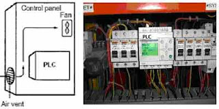
The small PLC in panel


Power lines & high-voltage equipment can cause electrical noise in the PLC; • Do not install the PLC in a panel or cabinet with high-voltage equipment • Allow at least 200 mm between the PLC and nearby power lines See the picture below;
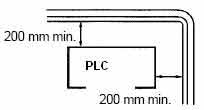
Make sure that the PLC can be accessed for normal operation and maintenance;
• Provide a clear path to the PLC for operation and maintenance. High-voltage equipment or power lines could be dangerous if they are in the way during routine operations
• The PLC will be easiest to access if the panel or cabinet is installed about 3 to 5 feet above the floor

2. Installing the CPU Unit and I/O Unit
The small PLC must be installed in the position shown below to ensure adequate cooling.
See the picture below;


Do not install the small PLC in either of the following positions.

The small PLC can be installed on a horizontal surface or on a DIN track. See the picture below;

Lower the small PLC so that the notch on the back of the PLC catches the top of the DIN Track. Push the PC forward until the lock snaps into place. See the picture below;

For the big PLC before installing, the Units have to compiled one by one. There is no single Unit that can be said to constitute a Rack PLC. To build a Rack PLC, we start with a Backplane. The Backplane for the Omron PLC is shown below.

The Backplane is a simple device having two functions. The first is to provide physical support for the Units to be mounted to it. The second is to provide the connectors and electrical pathways necessary for connecting the Units mounted to it. The core of the PLC is the CPU. The CPU contains the program consisting of the series of steps necessary for the control task. The CPU has a built-in power supply, and fits into the rightmost position of the Backplane.

The CPU of the big PLC has no I/O points built in. So, in order to complete the PLC we need to mount one or more I/O Units to the Backplane. Mount the I/O Unit to the Backplane by locking the top of the I/O Unit into the slot on the Backplane and rotating the I/O Unit downwards as shown in the following diagram. Press down on the yellow tab at the bottom of the slot, press the I/O Unit firmly into position, and then release the yellow tab.

The figure below shows one I/O Unit mounted directly to the left of the CPU.

I/O Units are where the control connections are made from the PLC to all the various input devices and output devices. As you can see from the figure above, there is still some space available on the left side of the Backplane. This space is for any additional I/O Units that may be required.The figure below shows a total of eight I/O Units mounted to the Backplane.

After the big PLC compiled in the backplane then the big PLC can be installed on the DIN Rail. The DIN Rail Mounting Bracket shown below is necessary for mounting the PLC to the DIN Rail.

The following diagram is a view of the back of the Backplane. Attach one Mounting Bracket to the left and right sides of the Backplane as shown below.

Mount the Backplane to the DIN Rail so that the claws on the Mounting Brackets fit into the upper portion of the DIN Rail as shown below.

Loosen the screws attaching the Mounting Brackets to the Backplane. Slide the Backplane upward as shown below so that the Mounting Bracket and Backplane clamp securely onto the DIN Rail. Tighten the screws.


3. Installing the Expansion Unit or Expansion I/O Unit
The Expansion Unit or Expansion I/O Unit are usually attached when amount of I/O devices to be controlled increase its amount over than capacities of the existing I/O Unit or attached when needed to a special need like temperature sensor. The following shown the example of Expansion Units.

Expansion Unit of the small PLC


Expansion Unit of the big PLC

For the small PLC use the following procedure when connecting an Expansion Unit or Expansion I/O Unit;Remove the cover from the CPU Unit’s or the Expansion I/O Unit’s expansion connector. Use a flat-blade screwdriver to remove the cover from the Expansion I/O Connector.


Insert the Expansion I/O Unit’s connecting cable into the CPU Unit’s or the Expansion I/O Unit’s expansion connector.


Replace the cover on the CPU Unit’s or the Expansion I/O Unit’s expansion connector.


For the big PLC use the following picture when connecting an Expansion Unit or Expansion I/O Unit;


4. Installing I/O devices
I/O devices are attached at the place have been determined in the work plan and wiring diagram. For switches are usually attached at the panel while the sensor, selenoid and motor is usually placed at the machine to be controlled.


5. Wiring and connections
Duct Work
Hanging Ducts If power cables carrying more than 10 A 400 V, or 20 A 220 V must be run alongside the I/O wiring (that is, in parallel with it), at least 300 mm must be left between the power cables and the I/O wiring as shown below.


Floor Ducts If the I/O wiring and power cables must be placed in the same duct (for example, where they are connected to the equipment), they must be shielded from each other using grounded metal plates.


Conduits if Separating the PLC I/O lines, power and control lines, and power cables, as shown in the following diagram.


I/O connections
Connect the I/O Devices to the I/O Units. Use 1.25-mm2 cables or larger The terminals have screws with 3.5-mm diameter heads and self-raising pressure plates. Connect the lead wires to the terminals as shown below. Tighten the screws with a torque of 0.8 N _ m.

If you wish to attach solderless type terminals to the ends of the lead wires, use terminals having the dimensions shown below.

The following diagrams show the input configurations. This input configuration depend on specification of the Input Unit will be used. See the specification before install.

The following diagrams show the input configurations. This output configuration depend on specification of the Output Unit will be used. See the specification before install.

Power Supply Wiring on The OMRON PLC

Power Supply Wiring on The OMRON PLC

The following example show the proper way to connect the power source to the PLC. Use 1.25-mm2 cables or larger. The terminal blocks have screws with 3.5-mm diameter heads and self-raising pressure plates. For connecting to the terminal blocks, use round crimp terminals for 3.5-mm diameter heads. Directly connecting stranded wires to the terminal blocks may cause a short-circuit.

Power supply wiring on the Omron PLC

Grounding
This PLC has sufficient protection against noise, so it can be used without grounding except for special much noise. However, when grounding it should be done conforming to below items. Ground the PLC as independently as possible. Class 3 grounding should be used (grounding resistance 100? or less). When independent grounding is impossible, use the joint grounding method as shown in the figure below (B). Use thicker grounding wire. Grounding point should be as near as possible to the PLC to minimize the distance of grounding cable.
See the picture below;

Checking the work and making the report
Inspecting installation
After Installation has been done then done inspection of the work quality and wiring. This matter is executed by checking every extension cables at devices and compared with the wiring diagram which has been prepared. Checking extension cables and devices are done by using the assistive equipment like the multimeter and testpen. Matters which require to be paid attention to in inspection for example:
• Whether all Units of the PLC and I/O devices have been attached truly?
• Whether all cables and connectors have been attached compactly according to the wiring diagram and jam in lickety split?
• Are there Loose terminal screws?
• Are there Loose connectors?


Testing installation
Several items which require to be tested in installation of the PLC for example;
Wiring input
Wiring input can be tested by connecting all input devices and see the indicator lamp on Input Units of the PLC. Wiring input of the PLC can be told goodness if the indicator lamp on Input Units is ON.
Wiring output
Wiring output can be tested by using force instruction to output terminal of the PLC. The instruction can be used without waiting the program has been made and can be separated without damage the existing program if the PLC has been programmed.
The following example show forcing at the Omron PLC;
  • Connect the Programming Console, set the mode switch to PROGRAM mode, and turn ON the PLC
  • Enter the password by press
  • Enter the force instruction by press

see the picture below;

Forcing instruction

Grounding Resistance, Insulation Resistance, Polarity
Grounding resistance, and polarity can be tested by using the Multimeter while insulation resistance can be tested by using the Mega ohmmeter. For the grounding resistance has to less than 100 ohm, for the insulation resistance has to more than 1 Megaohm/volt. The polarity of DC voltage require to be retested to prevent the happening of inversed polarity which can destroy the equipments.

Making the Report
The report is made for documentation. With the good documentation and depository of the good administration peripheral, we will be more easy to look for the archives nor things which we need.

Programmable Logic Controllers Configurations

Programmable Logic Controllers Configurations

Programmable Logic Controllers (PLCs) are microprocessor-based devices used to control industrial processes or machines. They provide advanced functions, including analog monitoring, control and high speed motion control as well as share data over communication networks.

Basic PLCs are available on a single printed circuit board. They are sometimes called single board PLCs or open frame PLCs. These are totally self contained (with the exception of a power supply) and, when installed in a system, they are simply mounted inside a controls cabinet on threaded standoffs. Screw terminals on the printed circuit board allow for the connection of the input, output, and power supply wires. These units are generally not expandable, meaning that extra inputs, outputs, and memory cannot be added to the basic unit. However, some of the more sophisticated models can be linked by cable to expansion boards that can provide extra I/O. Therefore, with few exceptions, when using this type of PLC, the system designer must take care to specify a unit that has enough inputs, outputs, and programming capability to handle both the present need of the system and any future modifications that may be required. Single board PLCs are very inexpensive (some less than $100), easy to program, small, and consume little power, but, generally speaking, they do not have a large number of inputs and outputs, and have a somewhat limited instruction set. They are best suited to small, relatively simple control applications.

Processor
The processor sometimes call a CPU Modules, as in the self contained units, is generally specified according to memory required for the program to be implemented. In the modularized versions, capability can also be a factor. This includes features such as higher math functions, PID control loops and optional programming commands. The processor consists of the microprocessor, system memory, serial communication ports for printer, PLC LAN link and external programming device and, in some cases, the system power supply to power the processor and I/O modules.

Mounting rack
This is usually a metal framework with a printed circuit board backplane which provides means for mounting the PLC input/output (I/O) modules and processor. Mounting racks are specified according to the number of modules required to implement the system. The mounting rack provides data and power connections to the processor and modules via the backplane. For CPUs that do not contain a power supply, the rack also holds the modular power supply. There are systems in which the processor is mounted separately and connected by cable to the rack. The mounting rack can be available to mount directly to a panel or can be installed in a standard 19″ wide equipment cabinet. Mounting racks are cascadable so several may be interconnected to allow a system to accommodate a large number of I/O modules.

Input and Output Modules
Input and output (I/O) modules are specified according to the input and output signals associated with the particular application. These modules fall into the categories of discrete, analog, high speed counter or register types. Discrete I/O modules are generally capable of handling 8 or 16 and, in some cases 32, on-off type inputs or outputs per module. Modules are specified as input or output but generally not both although some manufacturers now offer modules that can be configured with both input and output points in the same unit. The module can be specified as AC only, DC only or AC/DC along with the voltage values for which it is designed.

Analog input and output modules are available and are specified according to the desired resolution and voltage or current range. As with discrete modules, these are generally input or output; however some manufacturers provide analog input and output in the same module. Analog modules are also available which can directly accept thermocouple inputs for temperature measurement and monitoring by the PLC.

Pulsed inputs to the PLC can be accepted using a high speed counter module. This module can be capable of measuring the frequency of an input signal from a tachometer or other frequency generating device. These modules can also count the incoming pulses if desired. Generally, both frequency and count are available from the same module at the same time if both are required in the application. Register input and output modules transfer 8 or 16 bit words of information to and from the PLC. These words are generally numbers (BCD or Binary) which are generated from thumbwheel switches or encoder systems for input or data to be output to a display device by the PLC.

Other types of modules may be available depending upon the manufacturer of the PLC and it’s capabilities. These include specialized communication modules to allow for the transfer of information from one controller to another. One new development is an I/O Module which allows the serial transfer of information to remote I/O units that can be as far as 12,000 feet away.

Power supply
The power supply specified depends upon the manufacturer’s PLC being utilized in the application. As stated above, in some cases a power supply capable of delivering all required power for the system is furnished as part of the processor module. If the power supply is a separate module, it must be capable of delivering a current greater than the sum of all the currents needed by the other modules.

For systems with the power supply inside the CPU module, there may be some modules in the system which require excessive power not available from the processor either because of voltage or current requirements that can only be achieved through the addition of a second power source. This is generally true if analog or external communication modules are present since these require ± DC supplies which, in the case of analog modules, must be well regulated.

Programming Unit
The programming unit allows the engineer or technician to enter and edit the program to be
executed. In it’s simplest form it can be a hand held device with a keypad for program entry and a display device (LED or LCD) for viewing program steps or functions More advanced systems employ a separate personal computer which allows the programmer to write, view, edit and download the program to the PLC.

This is accomplished with proprietary software available from the PLC manufacturer. This software also allows the programmer or engineer to monitor the PLC as it is running the program. With this monitoring system, such things as internal coils, registers, timers and other items not visible externally can be monitored to determine proper operation. Also, internal register data can be altered if required to fine tune program operation. This can be advantageous when debugging the program. Communication with the programmable controller with this system is via a cable connected to a special programming port on the controller. Connection to the personal computer can be through a serial port or from a dedicated card installed in the computer.
 
Support : Creating by | PTNGA | Metal
Copyright © 2011. Mitsubishi & Fuji Electric Indonesia - All Rights Reserved
Created by Website Published by Product | Distributed By: Toko
Proudly powered by Blogger